My favorite house projects are the ones that justify my favorite “toys”. I recently had a chance to justify my 3D printer purchase. Before getting into the weeds, let me share my joy in this project with you:
I can sit in my house and move pixels on a screen and have a <$1000 machine turn those pixels into a physical plastic thing with sub-millimeter precision in a few hours. WE LIVE IN THE FUTURE. This is what’s amazing about 3D printing to me–not printing models from Thingiverse, but designing and fabricating super-specific parts to solve my own unique problems.
Problem
Upon having a child, you find you need to restrict access to many places in your house. My house has stairs, so we obviously needed a stair gate. Our stairs have rough stone along one wall that’s wonderful aesthetically… but a huge pain when installing a stair gate. I wanted to use a pressure-type gate (i.e., one that is fixed in place by pressing against the walls it’s situated between) to be able to remove it occasionally with little fuss.
Such gates reasonably assume a flat wall surface to press against. The rough stone wall in our stairwell did not satisfy this assumption. After noodling on this over a few showers, I came up with an idea to turn this toilsome task into a fun side project–I could design and print an “adapter” to provide a flat surface over the rough stone.
Approach
The adapter as imagined had three important aspects: a rough side, a flat side, and a screw hole. I’ve designed models/parts for 3D printing in Fusion 360 and knew how to handle the flat side and screw hole. The rough side was the new, fun part.
The purpose of the rough side is to match the face of the rough stone closely enough that the pressure load from the gate is evenly distributed. This rough surface is far too complex to eyeball a model; I needed something better.
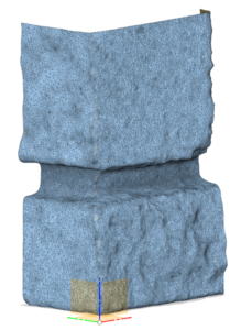
After a little research, I found that my wife’s iPhone was quite capable of capturing the rough face as a high quality 3D model. I had assumed this process would use iPhone’s (then) new LIDAR capability, but I think the surface was fine enough that the app used photogrammetry (i.e., magic using many photos of a 3D surface/object). Anyway, the result was excellent–I had a detailed 3D model of the rough surface.
Design
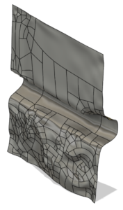
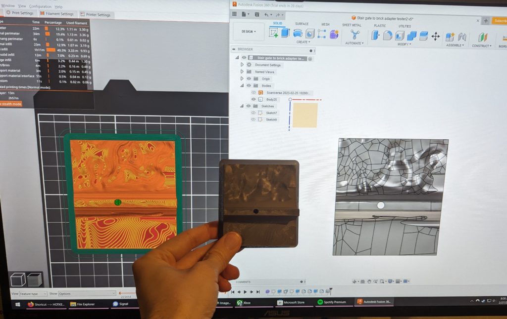
Next, I needed to ingest this 3D model in Fusion 360. I wish I had a list of steps to give you for this, but it was a huge pain and I’m not sure how I did it. Fusion 360 is awful with complex meshes like this one that represents the rough stone face (which I’ll call the stone mesh).
I struggled to get the stone mesh to be a valid surface–that is, one that is continuous and solid and has no holes or little tiny funky triangle tangles. I applied simplify and repair and organic tools until I finally got it to work and never touched it again. I’ve heard there are much better tools for working with meshes, but I chose to suffer with the devil/tool I knew.
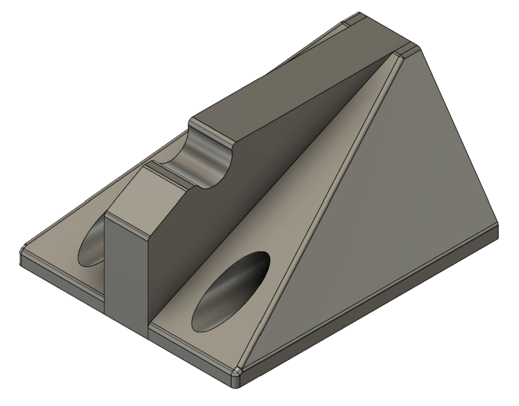
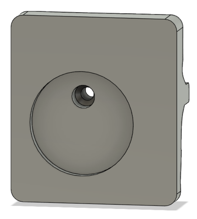
With the stone mesh finally in a good state, the rest of the adapter was easy. I created a rectangular prism with a circular inset for the gate arm to sit in/press on. I set the screw hole (for fixing the adapter to the stone) into the inset.
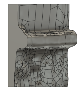
There was a little interesting design resulting from the height of the gate–the upper gate arm happened to be at the same level as a mortar break between stones. I had to add support through to the mortar because the rest of the part was not strong enough to support gate pressure spanning the mortar break (see image).
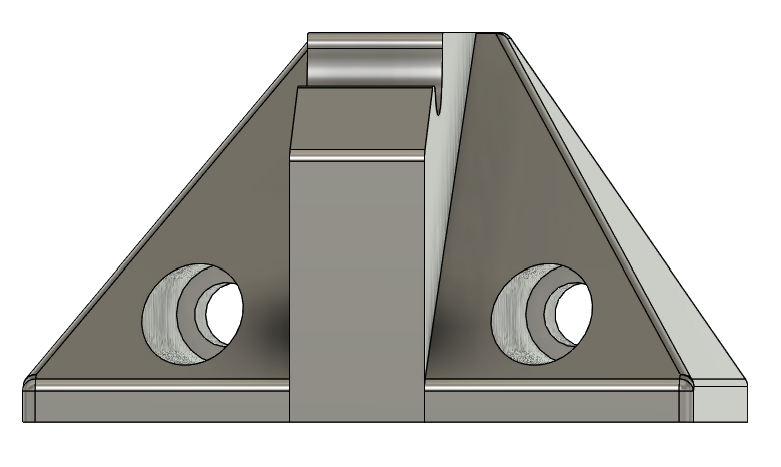
My decision to secure the adapter into the mortar kinda bit me here because I also needed a big hole in this funky mortar support area. So, I wanted as small a hole as possible, but the smaller the diameter of hole, the shorter the screws (tapcons) available to use would be, which meant I needed more bore/sink in the hole, which meant less adapter material between the screw head and mortar, and if there was too little material the material would crush. And if I increased the screw/hole diameter, the hole burst from the mortar support material too soon. I sorted this out through trial and error.
Testing
This took some trial and error iteration. I had assumed I could just intersect the stone mesh with the adapter body and get a surface that would perfectly fit in the mortar, but either the mesh wasn’t good enough or my printing wasn’t precise enough. I had to create some “give” in the part, both to get a bit of it to touch the mortar and to get it to fit over the rough stone.
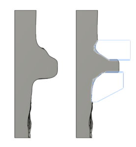
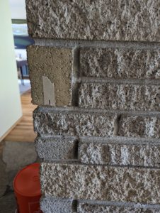
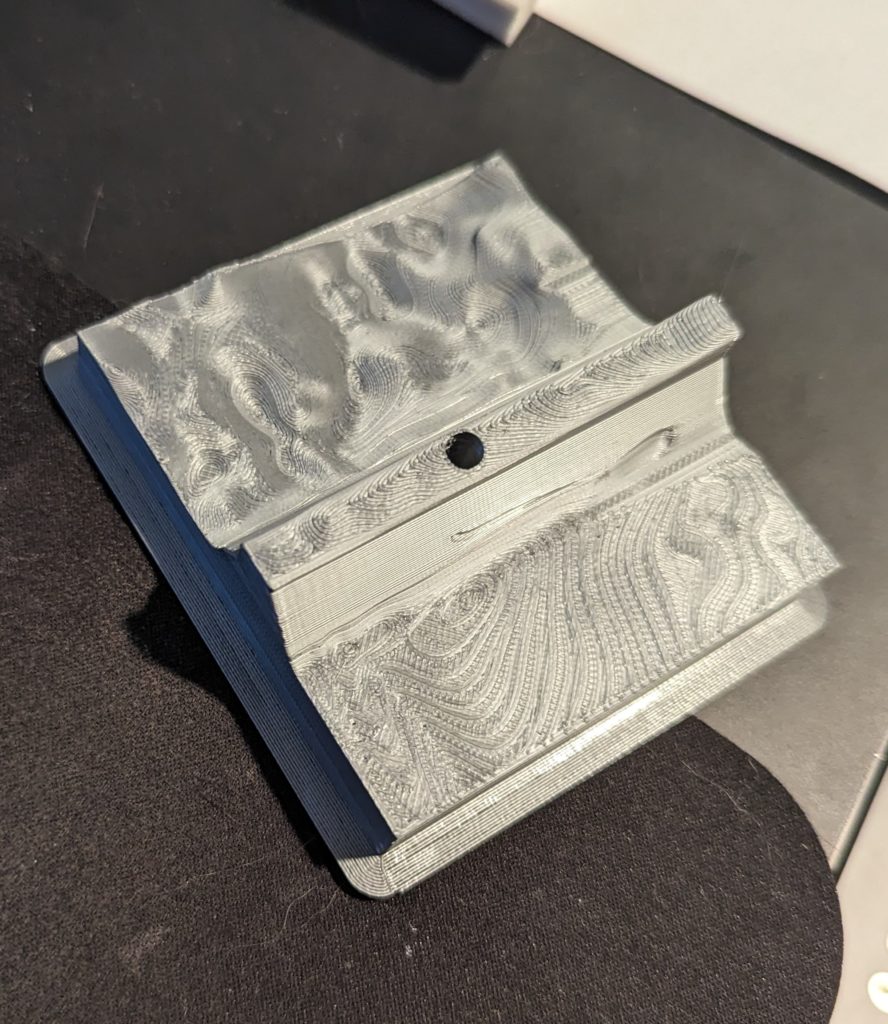
To get the adapter to touch mortar, I removed material around the edges of the bricks nearest the mortar break (see image). I eyeballed this because some parts of the adapter had more space to give and some had less, and I wanted as much material as possible supporting through to mortar.
The initial models didn’t interface with the rough stone at all. I fixed this by extruding into/subtracting from the rough face of the adapter bit by bit (again, huge pain because it involved a complex mesh) until the adapter “clicked” into place.
I can’t describe to you how utterly satisfying this click felt. When placing the adapter, I had to hunt around to find where it was supposed to go, but once I found it, everything lined up perfectly so that it fell in, clicked (by feel, not audibly), and strongly resisted lateral movement as long as it was pressed against the stone. The complex surface not only spread load across the stone, but created tons of frictious surface area. chef’s kiss
The rest of testing/iterating was little stuff like aligning the screw hole with a good mortar spot, tweaking measurements, adding fillets to make this thing a little more pleasant to look at, putting supports in the right places so the screw hole would print well, cutting material where possible to reduce its depth/profile, tweaking the model in the slicer to add 100% infill to the most stressed/compressed areas, and slicing with variable depth layers to print the boring/non-interfacing layers fast and thick, but the interfacing layers slow, thin, and detailed.
It was really fun to watch the interfacing layers print, like watching a mountain deposited layer by layer. Except this mountain had a countersunk bore hole in it. Also my printer makes fun noises when it’s moving the print head in a complex path (i.e., not in a straight line).
Installation
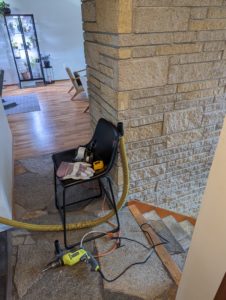
With everything set and measured twice, I dragged out my hammer drill and put a hole in the mortar. I set the adapter in place over that hole, drove the tapcon in (extremely nervously, balancing securement tension and “when will my part crush?”), and gave it a rigorous “grab and wiggle” test. All good!
I installed the rest of the gate around the installed adapter since the adapter would be painful to relocate. With the flat gate arm pads secured, I put the gate in place and tensed the gate arms to “toddler resistant” pressure, listening for crush sounds anxiously.
Aftermath
The adapter has been in place for months and continues to serve admirably. I used to look at it every time I passed with a swell of pride. But now, I can’t remember the last time I looked at it. I think that’s a good thing. For some parts, the highest honor is to go unnoticed.
Appendix
A few other super-specific parts I’ve worked on.
Rear rack bike light mount
I’ve had a Fly6 rear-facing camera on my bike for a loooong time. When I added a rear rack to my bike, its view got obstructed. The Fly6 is made to attach to a seat post, but I wanted to put it on the back of my new bike rack. I designed this small part to fit onto the rack’s rear attachment point with a few holes. The other end of the part provides a seat post-like surface for the camera mount.
This is one of my first designs in Fusion 360, so it’s a little rough, but it works. I printed it with ABS for UV resistance and durability. It’s been working for four years.

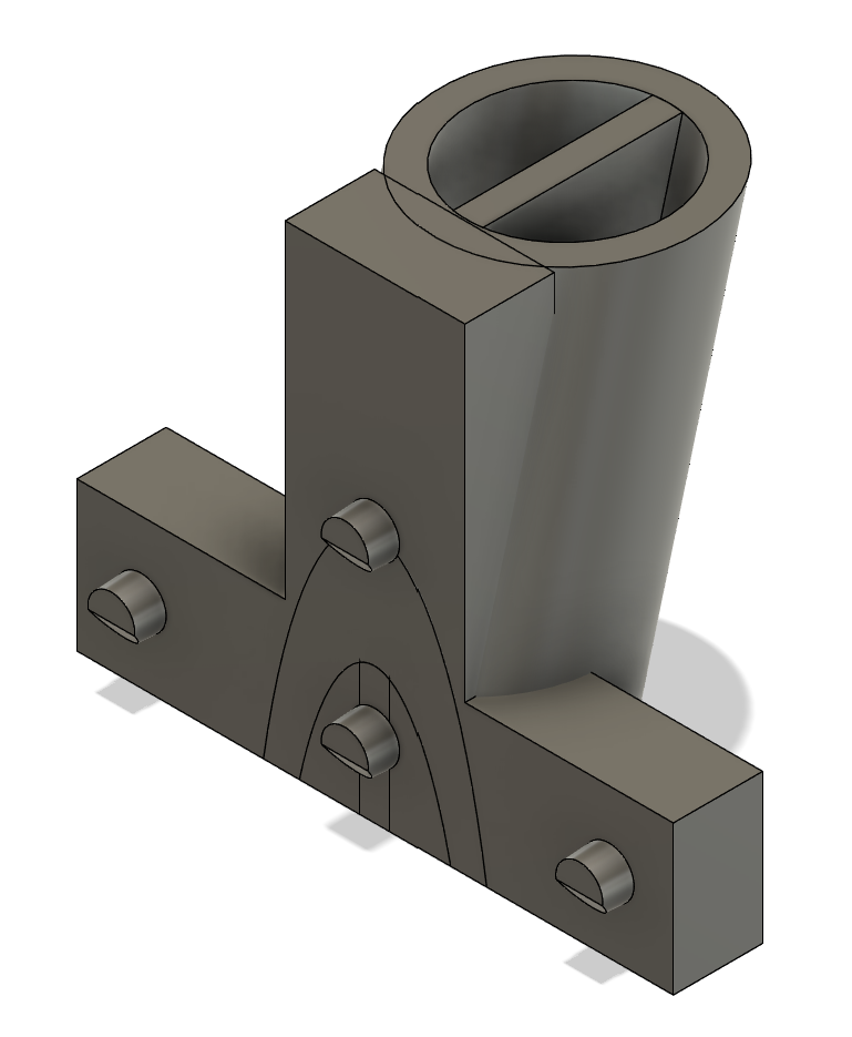
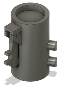
Model rocket landing leg
Being a big fan of BPS.space and inspired by his model rocket propulsive landing attempts, I tried developing a leg for amateur rockets to absorb landing energy. My lack of mechanical engineering degree shows here, but it was a fun project.
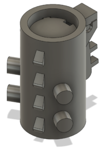
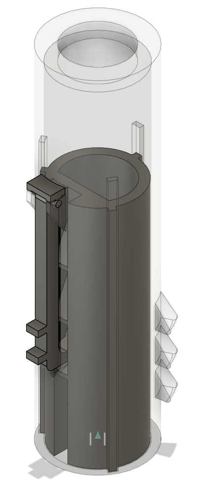
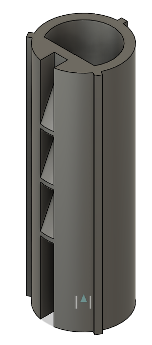
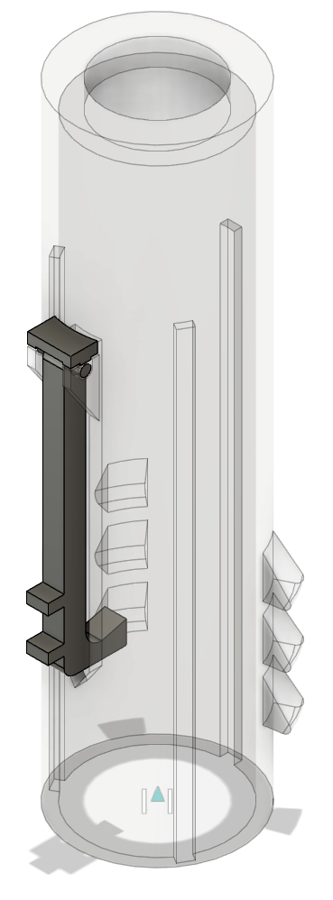
The design I settled into was to have a small inner body (piston) begin extended, then move up into the outer cylinder as it hit the ground. I figured I could rely on air pressure for damping force by covering the exposed top of the cylinder and making a small hole for air to escape.
I wanted the dissipated energy to not rattle around the part during compression/landing, so I added a pawl to the cylinder that would prevent the piston from extending again upon landing. Being able to use terms like “pawl” made me feel like a real engineer.
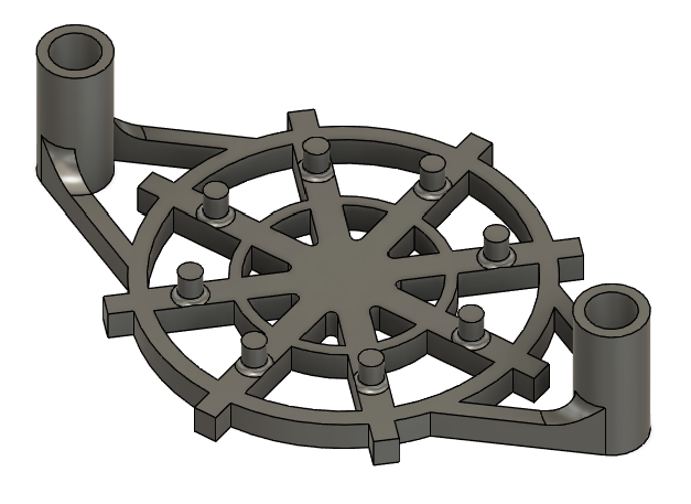
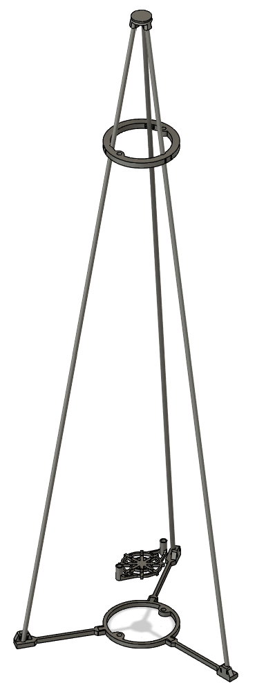
I made a longer version with more travel and a test stand so I could repeatedly and consistently test these things. I was never able to overcome the friction between the piston and cylinder. Getting these small things to work with small forces was tough. But I got to order stuff from McMaster-Carr like a real engineer.
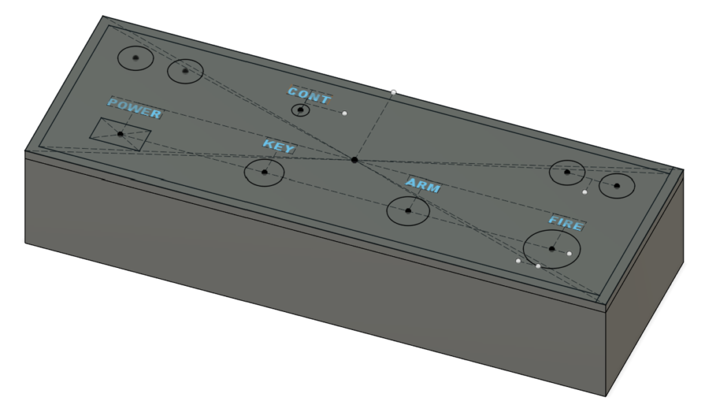
I also made my own super-cool launch controller. I was starting to experiment with snap fitting and using models from part providers like Sparkfun in this design.
Gate rest
In another house, we had a stair gate so we could keep dogs in one area or another. I built this little part to screw into the baseboard where the gate sat when fully opened. This was my first Fusion 360 design and it shows. I still love it and am a bit proud of it though.